
-

Envoyez-nous un courriel
sale@lscmagnetics.com -

Numéro de contact
+86 -13559234186
Envoyez-nous un courriel
sale@lscmagnetics.comNuméro de contact
+86 -13559234186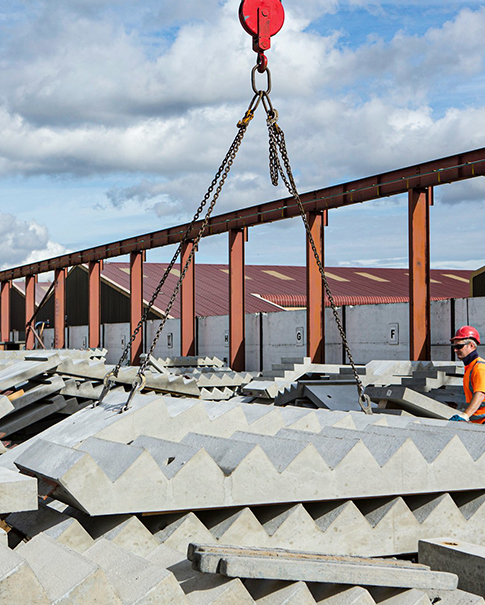

Fonctionnement des ancrages de levage dans les éléments préfabriqués : Guide technique
Jan 30, 2026Avec l'évolution de la construction moderne, les éléments préfabriqués en béton jouent un rôle de plus en plus crucial. L'ancrage de ces éléments constitue un fondement essentiel pour garantir la stabilité et la sécurité globales de la structure.
Les éléments préfabriqués sont des composants de construction fabriqués en usine puis installés sur le chantier. Pour garantir des liaisons solides et fiables, tant entre les éléments préfabriqués qu'avec la structure coulée en place, des systèmes d'ancrage spécialisés sont indispensables. Cet article examine les principes de fonctionnement, les cas d'application et les critères de sélection de ces systèmes. ancres de levage dans la construction préfabriquée.

Fonctionnement : Les mécanismes du transfert de charge
Un ancrage de levage est un dispositif mécanique intégré qui crée un chemin de charge défini entre l'élément en béton et la grue. Lors du coulage, l'ancrage, généralement forgé en acier au carbone haute résistance ou en acier inoxydable, est placé dans le coffrage et enrobé de béton. Au fur et à mesure que le béton durcit, il forme une liaison mécanique robuste avec la géométrie spécifique de l'ancrage.
Le transfert de charge s'effectue en trois étapes distinctes :
1. Engagement direct : La tête d'ancrage, qu'elle soit sphérique, en forme d'œil ou filetée, s'engage avec l'embrayage ou le crochet de levage, recevant la force de traction directe.
2. Transmission de la force : Cette force est transmise le long de la tige de l'ancre jusqu'à son extrémité encastrée.
3. Répartition de la charge : L’élément crucial est que la base élargie ou les ailettes d’expansion de l’ancrage transfèrent la charge au béton environnant. Ce transfert s’effectue principalement par pression d’appui et formation d’un cône de cisaillement dans le béton, plutôt que par simple frottement.
Types d'ancres et leurs utilisations
En fonction du composant et des exigences de levage, les ancrages sont disponibles sous plusieurs formes :
- Inserts filetés : Idéaux pour les éléments plus fins, ils offrent une installation simple.
-Boucles/anneaux de levage: Offrent une flexibilité multi-angles et sont courantes dans les panneaux muraux.
-Ancrages à plaque: Assurer une répartition stable de la charge pour les poutres et les colonnes de grande portée, en évitant les contraintes concentrées.
Chaque modèle est conçu avec précision pour garantir que les contraintes dans le béton restent dans une plage de sécurité pendant le levage.

Principaux scénarios d'application et guide de sélection
| types de composants préfabriqués | Types d'ancres principales recommandés | Scénarios d'application et explications |
| panneaux muraux en béton préfabriqué | Clous/écrous de levage pré-encastrés, ancrages à plaque | - Panneau mural standard : 4 à 8 clous de suspension pré-encastrés sont disposés symétriquement en haut pour le levage vertical. - Grand panneau intégré d'isolation et de décoration : des ancrages à plaque sont utilisés pour répartir la charge et éviter les dommages localisés. - Panneau décoratif à paroi mince : Des vis autotaraudeuses (ancrage sur poteau) ou de petites pièces pré-encastrées peuvent être utilisées. |
| Dalles de plancher/escaliers préfabriqués | Clous/écrous de levage pré-encastrés et anneaux de levage pour barres d'armature | - Grands panneaux intégrés d'isolation thermique et décoratifs : Utiliser des ancrages de type plaque pour répartir la charge et éviter les dommages localisés. - Panneaux décoratifs à parois minces : peuvent utiliser des vis autotaraudeuses (ancrage sur poteau) ou de petites pièces encastrées. - Dalles de plancher composites : Elles comportent généralement 4 points de levage, utilisant des écrous pré-intégrés, ce qui permet d'obtenir une surface lisse après l'installation. - Escaliers préfabriqués : Les points de levage sont souvent situés près de la plateforme supérieure, ce qui permet aux escaliers de former naturellement un angle lors de l’installation. Le centre de gravité doit être calculé. |
| Les éléments structuraux tels que les poutres et les colonnes | Clous/écrous de suspension encastrés, extrémités de tendons précontraints | - Colonnes préfabriquées : 2 à 4 points de levage symétriques sont prévus en partie supérieure pour le levage vertical. - Grandes poutres précontraintes (dalles en T doubles, poutres en I) : Les points de levage sont généralement situés aux deux extrémités ou à proximité ; parfois, les extrémités précontraintes sont utilisées directement. - Galeries de canalisations et segments de tunnel : des ancrages à plaques doivent être utilisés pour supporter uniformément les énormes forces de levage. |
| Composants de forme irrégulière/composants municipaux | Utilisation combinée, outils de levage spéciaux | - Tunnels et segments de tunnels techniques : des ancrages à plaques doivent être utilisés pour répartir uniformément les énormes forces de levage. - Balcons et baies vitrées de forme irrégulière : sur la base de l’analyse du centre de gravité, plusieurs supports pré-encastrés doivent être placés dans des zones robustes, et des poutres d’équilibrage ou des systèmes de suspension multipoints peuvent être utilisés pour assurer la stabilité. |
| Feuille mince/petits composants | Vis de levage autotaraudeuses, petites pièces encastrées | - Plaques minces de moins de 100 mm d'épaisseur : profondeur de pré-encastrement insuffisante ; les vis autotaraudeuses sont un meilleur choix pour la post-installation. - Bordures, petits pavés : des pinces spéciales peuvent être utilisées à la place des ancrages. |
Le choix des points d'ancrage dépend du type, du poids, de la forme, du centre de gravité et du processus de fabrication du composant. Cependant, une mauvaise utilisation demeure une cause majeure de défaillance. Les erreurs courantes incluent :
- Sélection incorrecte du type : L’utilisation d’ancrages conçus pour des sections épaisses dans des panneaux minces, ou pour des levages de bord/biseau, peut entraîner une défaillance.
- Incompatibilité de l'équipement : L'utilisation d'un embrayage de levage non entièrement compatible avec la tête d'ancrage entraîne un engagement partiel et une répartition inégale de la force.
Levage prématuré : Le levage avant que le béton n’ait atteint sa résistance spécifiée est dangereux. Un durcissement irrégulier, réalisé dans des délais serrés, peut rendre le béton autour de l’ancrage trop fragile, provoquant une rupture avant que l’acier n’atteigne sa capacité.
- Mauvais positionnement : les ancrages placés trop près d’un bord, avec un encastrement insuffisant ou dans un béton mal compacté créent des concentrations de contraintes, faisant du béton le maillon faible.
Principes fondamentaux de conception et de sécurité
1. Conception calculée : La quantité, la taille et l'emplacement des ancrages doivent être calculés par un ingénieur en structure, en tenant compte du poids du composant, d'un facteur dynamique (généralement 1,5), de la résistance du béton et de l'angle de levage.
2. Centre de gravité : Les points de levage doivent être disposés de manière à ce que leur ligne de connexion passe par ou au-dessus du centre de gravité du composant afin de garantir des levages stables et équilibrés.
3. Prévention de la rupture conique : Le principal mode de défaillance est la fissuration du béton en forme de cône autour de l’ancrage. Un espacement adéquat entre les ancrages et une distance suffisante par rapport aux bords sont nécessaires pour éviter que ces cônes ne se rejoignent ou n’atteignent la surface.
4. Angles de levage sécuritaires : lors de l’utilisation d’élingues, l’angle horizontal doit être pris en compte. Des angles plus petits augmentent considérablement la force exercée sur les points d’ancrage ; les angles inférieurs à 45 degrés sont strictement interdits.
5. Assurance qualité : Seuls des ancrages certifiés à haute résistance et conformes aux normes en vigueur (par exemple, GB/T 37610) doivent être utilisés. L’utilisation d’ancrages de fortune fabriqués à partir de barres d’armature pliées est inacceptable.
ÉTIQUETTES :
Whatsapp : +86 -13559234186
E-mail : sale@lscmagnetics.com
Tél : +86 -13559234186